The core of the IQ Power System is the Control Station which includes a full color touch screen designed with an intuitive interface and user-friendly features that help you monitor and control the system globally or by device.
The Control Station provides information you can rely on; including system name, status, output and current. Also shown are upstream and sensor bar data for operator safety and verification.
The Control Station offers upstream and downstream charge readings. Using the Sensor Bar allows the output of the power supply to be adjusted dynamically resulting in optimized static neutralization.
The Control Station incorporates several relay output choices to suit desired alarm methods for streamlined operation and maximum productivity. Global relays as well as individual IQ Power BPS relays are accessible for both warning and fault user selectable alarm thresholds.
Features and Benefits
- Full PLC integration
- Data logging and retrieval
- 10” full color touchscreen
- User set alarm thresholds
- 10 unique device addresses
- Monitor static bar cleanliness, ion output, and bar status; monitor static charge with the Sensor bar
| Input Power Rating |
100 - 240V ~ 50/60Hz
4A Max. (IEC 320 inlet) |
| Profile Dimensions |
292mm L x 197mm W x 114mm H (11.63" L x 7.75" W x 4.5" H) |
| Operating Temp. |
43°C (110°F) |
| Material |
Steel, blue epoxy powder coated |
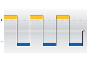
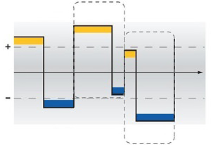
Balance Modes
Fixed Mode: consistent time and amplitude
Auto-Tune Mode: dynamic time and amplitude
Data logging is sometimes necessary in critical areas. Therefore, the IQ Power Control Station incorporates user selectable time interval data points in addition to event logging capabilities. Couple that with simplified data retrieving methods via USB or FTP for ultimate convenience. The Control Station provides operating details of each device in the system upon clicking on the individual icons from the Global View screen. Device details include system name, status, output and current. Also shown are upstream and downstream charge indicators for operator safety and verification. An optional web speed encoder can provide automatic web speed readings if desired.